Quantcast
Channel: usb | Battery Guide
Viewing all 395 articles
Browse latest View live

PIC’ing the MAX3100: Adding USB to a PIC Microcontroller Using the MAX3100 UART using pic microcontroller

$
0
0

Abstract: USB has just become easy to implement. This application note eases equipment designers into USB by allowing them to continue to transmit and receive data using the familiar UART frames of the MAX3100 UART. A UART-to-USB converter IC and operating system driver will take care of all of the USB complexity. The application note describes all of the software and hardware you need in order to transmit and receive data using the MAX3100 over USB.

PIC'ing the MAX3100 Adding USB to a PIC Microcontroller Using the MAX3100 UART

Background

The UART (universal asynchronous receiver transmitter) has been the standard serial port framer ever since IBM’s original PC motherboard used the Intel 8250 UART. Decades later, the UART continues to be widely used due to its reliability and simplicity.

The universal serial bus (USB) has largely replaced the standard serial port as the way to connect devices to a PC because it is simpler, more foolproof, and faster. But while USB makes connection easier for the user, it presents the designer with additional challenges. Many designers continue to use the UART with the standard serial port, waiting for products that make USB easier to implement. Happily, that day has arrived. A USB interface can now be achieved using the MAX3100 and a UART-to-USB converter. The designer works with the familiar UART frames of the MAX3100 UART and the UART-to-USB converter IC and an operating system driver take care of the complexities of USB.

The MAX3100 is the first UART targeted specifically for microcontroller systems. Its SPI™/QSPI™ compatible interface allows the MAX3100 to be used with almost any microcontroller. The SPI/QSPI interface is ideal because it is easy to implement with either an on-chip SPI/QSPI peripheral or just 4 GPIOs. The MAX3100 supports SPI data rates up to 4.2MHz and its UART supports baud rates up to 230kBd.

This application note eases equipment designers into USB by allowing them to continue to transmit and receive data using standard UART data frames.The information below describes all of the software and hardware you need in order to transmit and receive data using the MAX3100 over USB.
PIC'ing the MAX3100 Adding USB to a PIC Microcontroller Using the MAX3100 UART

A UART-Based USB Design

The application circuit shown in Figure 1 consists of the MAX3100 UART, a FT232BM UART-to-USB converter, a 93C46 serial EEPROM, and a PIC16F84 microcontroller. Since the PIC16F84 does not have any internal USB or UART peripherals, the MAX3100 makes the perfect external UART peripheral. The program, shown in Listing 1, interfaces the PIC16F84 to the MAX3100 via SPI.


For more detail: PIC’ing the MAX3100: Adding USB to a PIC Microcontroller Using the MAX3100 UART

The post PIC’ing the MAX3100: Adding USB to a PIC Microcontroller Using the MAX3100 UART using pic microcontroller appeared first on PIC Microcontroller.


USB PIC Programmer

$
0
0

This page is dedicated to everybody needs to program a PIC (Microchip) device via USB port. Looking on the web for ready-to-use  projects, I found a good one called Open Programmer, coming with several schematics, PCBs and Open Source code. The original link is http://openprog.altervista.org/OP_ita.html

What concerned me was the need to mount, on the mainboard, a specific socket board depending on the model of PIC being programmed. Moreover, the proposed layout did not meet my personal “compact look” ideas. So, I propose here a small layout version of that circuit, adopting a single smart on-board ZIF socket. This version sacrifices many non-PIC microcontroller models. I will thank everybody proposing a larger range implementation, suitable to program Atmel and other devices. Anyway, if your goal is to program PIC devices, you are on the good site.

A small box, a USB connector, a ZIF socket, two leds. That’all in my compact proposal.

USB PIC Programmer

Description

The details are available on the original project mentionned above. Hereafter, I shown my Compact version, with a schematic, PCB layout and instruction for assemby and inserting it in a very common little plastic box. At the bottom of this page, I supply a copy of the program to load on the PIC18F2550 used to manage the programming functions, as well as a copy of the PC side program. I tested the program up to Win-8 without problems. Take into account that, on the original site, a newer version of both Firmware and Software is available.

Schematic

Schematic USB PIC Programmer

Assembly

Build first the main module using low profile components being under 10 mm of height from the PCB surface, since a second board will be mounted over that one. Mount 4 ten millimeters height columns to allow the final assembly of the second board. Use low profiles parts to fix the columns, otherwise some manual metals removal can be needed to reduce the occupation on the copper side.

For more detail: USB PIC Programmer

The post USB PIC Programmer appeared first on PIC Microcontroller.

Basic circuit for PIC18F24J50 or PIC18F26J50 to work over USB

$
0
0

The basic circuit below will work with any PIC18F2xJ50 microcontroller. You just have to upload the appropriate firmware. Go to Downloads section to find firmware hex files for the microcontroller and the resonator you would like to use. PIC18F24J50 firmware v2.6.3 – all subversions.zip contain the following general use subversions: 4 MHz, 8 MHz, 12 MHz, 16 MHz and 20 MHz, and the following subversions for K8055 adapter: 4 MHz, 8 MHz, 12 MHz, 16 MHz and 20 MHz. PIC18F26J50 firmware v2.7.8 – universal.zip or later enables a wider range of settings. The package contains PC USB Projects HEX Editor v3.0 which makes it possible to set new EEPROM defaults before programming a HEX file.Basic circuit for PIC18F24J50 or PIC18F26J50 to work over USB

Yes, the basic circuit may also serve as a super speed microcontroller programmer (you must manually select option 02 – Super speed K8055 or K8055N programmer in PIC Programmer aplication, or set VID = 10CF (hex)). You just need to use a small piece of PCB to solder a DIP socket and a few resistors and two transistors and two capacitors. Don’t mind about the circuit in the plastic box. It is K8055, but you don’t need it! Use PIC Programmer v2.6 and above for PIC18F2xJ50 microcontroller with v2.2 firmware or later, and previous versions of the application for PIC18F2xJ50 microcontrollers with any versions of the firmwareBasic circuit for PIC18F24J50 or PIC18F26J50 to work over USB schematic

If you would like to use the basic circuit for PIC18F2xJ50 microcontroller programming, just go to subsection 4.b and build the adapter initially intended only for K8055 and K8055N boards. The adapter also works perfectly, if you stick it between the basic circuit DIP socket and the PIC18F2xJ50 microcontroller that you are going to use as a programmer for another PIC2xJ50 microcontroller. You may also use the originally programmed Velleman PIC18F24J50 microcontroller with the basic circuit, if you build it with 4 MHz crystal resonator and appropriate capacitors. See subsection 5.c. to get details on choosing the right capacitor values.


For more detail: Basic circuit for PIC18F24J50 or PIC18F26J50 to work over USB

Current Project / Post can also be found using:

  • pic nasta lans
  • pic16f877a network

The post Basic circuit for PIC18F24J50 or PIC18F26J50 to work over USB appeared first on PIC Microcontroller.

A Minimal USB CDC ACM aka Virtual Serial Port

$
0
0

This page introduces a minimal firmware that implements a USB Virtual Serial Port for Microchip PIC18F4550 processor.

The code has been optimized to use minimal amout of memory (both Flash and RAM) and tuned to work well with the Free SDCC C-compiler.

The code size is less than 2500 bytes and it requires about 230 bytes of RAM memory and it is capable of transferring almost 1 MB/sec (if only the PIC could generate any data at that speed!).

Why Virtual Serial Port

One of the hurdless that faces anyone who wants to interface a modern PC with the real physical world is the fact that most new computers have neither a serial port nor a parallel port that could be utilized to interface with external world. Most come only with USB and Etherner connections.

While USB standard is realy not that bad once you get into grips with the basics, it can be very intimidating. To make matters worse using USB often requires writing device drivers which can be even more intimidating. If you want to support the most common operating systems, Mac OS X, Linux or Windows, the task just gets bigger, easily beyound the resources of a lone developer.

But if you make your device appear as virtual serial port then the drivers will be provided by the courtesy of the operating system ie all the operating systems have built in drivers for serial ports.

A Minimal USB CDC ACM aka Virtual Serial Port True, there are libraries, I especially want to mention libusb , which make it relatively easy to access and develop a class of USB devices without writing drivers. And libusb is cross platform which I like a lot. Still it is an other dependency for your project and requires a native library to be linked with your host side application which is more work if you want to do cross platform application development with languages like Java, as I do.

Serial ports are easily accessible from various programming languages including C/C++, Python, Java, VisualBASIC etc.

Using the CDC ACM library

It sounds a bit grand to call this a library when in reality it is just one source code file and a three files with USB related ‘#define’s. I’ve created a ready to compile sample project that implements a virtual serial port that just echoes back everything you send to it. You can download the source code from here.

A word of warning about the source code: it was taken from a project that is fully functional but I had to clean it up a bit and remove some personal stuff. It compiles and there is a high probability that it works but I have not had the time to test it after the clean up. If you find any problems, please let me know.

Prerequisites

In priciple you should obtain your own PID and VID for your device from the USB consortium (or more easily from Microchip) but for simple testing and development it is ok to use what I have in the code ie Vendor id = VID = 0x0408 and Product id = PID = 0x000A.

To use the library you need to have ‘GNU autotools’ and ‘SDCC’ installed and in your ‘path’. You can of course compile the code without the autotools as there are just half a dozen files to compile. To program the firmware into the device you need the Microchip PICKit2 programmer and the ‘pk2cmd’ software that supports it on the ‘path’. If you don’t have the PICKit2 you realy should get one, at USD 35 it is a steal and it is supported on Linux, Windows and Mac OS X.

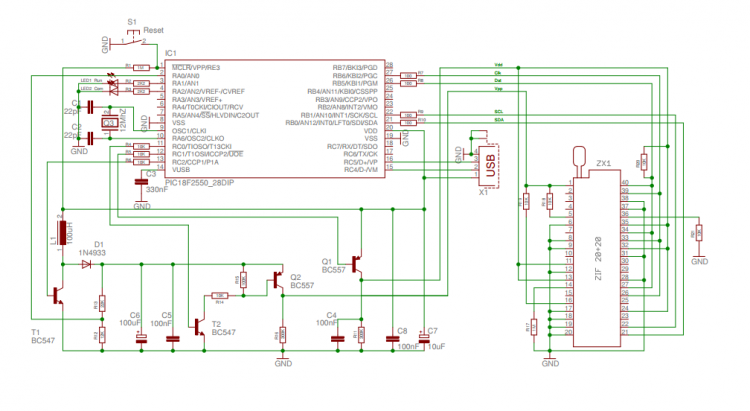
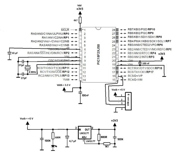
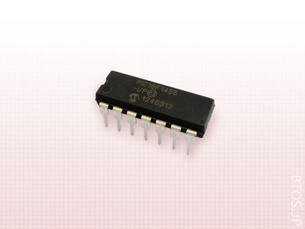
And naturally you need a PIC18F4550 device with 4 MHz xtal. It is also possible to use the other PIC18F series devices and crystals but some changes to the link and config options maybe necessary.

Compiling

To compile the code unzip the project into a directory and just cd to the directory where you have the code and type make. This should compile the code and program it to the device if you have the PICKit2 in readiness. The object code and resulting hex file will be placed in a directory obj parallel to the source directory.

Testing

To test it you need a terminal emulator. Plug your device to the USB port, open the terminal emulator, select the correct port and everything you type should be echoed back to the terminal.

Testing on Mac OS X

In Mac OS X type ls /dev/tty.usb* to get a list of USB virtual serial ports and then use the built in screen terminal to talk to it.

For example:

ls /dev/tty.usb* /dev/tty.usbmodem5d11 screen /dev/tty.usbmodem5d11

Testing on Linux

In Linux type ls /dev/ttyACM* to get a list of USB virtual serial ports and then use the built in screen terminal to talk to it.

For example:

ls /dev/tty.ACM* /dev/tty.ACM0 screen /dev/ttyACM0

Testing on Windows

In Windows you need to install an .inf file that will associate your device with the built in driver.

To install the ‘driver’ plug in the device and go to the Device Manager. Look for an ‘Unknown device’ and select ‘Properties’ for that device, then select ‘Install Driver’, browse to the cdcacm.inf file which is included with the project files.

Note the file has not been tested after clean up so there maybe some errors.

Also note that if you change the PID/VID of the device (and in the long run you should) then you need to update the cdcacm.inf file and re-install it.

After succesfull installation the device should appear as a COM port and you can use a terminal emulator such as PuTTY or TeraTerm to talk to it.

// send six bytes ie 'Hello\n'
   while (usbcdc_wr_busy())
      /* wait */;
   cdc_tx_buffer[0]= 'H';
   cdc_tx_buffer[1]= 'e';
   cdc_tx_buffer[2]= 'l';
   cdc_tx_buffer[3]= 'l';
   cdc_tx_buffer[4]= 'o';
   cdc_tx_buffer[5]= '\n';
   usbcdc_write(6);
   }

Understanding the Library

The library realy is simple to use, basically there are two functions and two buffers for transferring the data in and out of the device, there is a function that needs to be called periodically to poll the USB bus, there is a function to initilize the library and auxiliary functions to implement standard putc/getc functionality.

Note that the library code is written from the device point of view, ie ‘tx’,’put’ means that the device sends something to the host which maybe confusing because on this is called ‘input’ direction in USB terminology and the host code would use ‘read’ functions to receive the data. Just thought I’d mention this.


For more detail: A Minimal USB CDC ACM aka Virtual Serial Port 

The post A Minimal USB CDC ACM aka Virtual Serial Port appeared first on PIC Microcontroller.

pic18f2550 Microcontroller Project Board

$
0
0

The new PIC18F2550 Project Board was designed as the development platform for student projects.
board lcd
The board features

MCU: PIC18F2550 with external xtal,
ADC: one channel 0-2.5V sigma-delta converter, Linear Technology LTC2400/LTC2420,
6-channal 10-bit ADC 0-5V,
Display: Two connectors for text LCD or GLCD,
USB: onchip USB port with type B connector,
Power supply: onboard low dropout regulator, rechargeable battery,
Code programming: 10-pin header for In Circuit Loader.

The board platform is suitable for developing the microcontroller based instrumentation. Students may build the signal conditioning board, plugs it to PIC project board, develops the code and programs it with loader cable easily.

schematic circuit

Hardware

The MCU is 28-pin PIC18F2550 with external xtal as the option. We can use internal oscillator. The loader uses only three pins, PGD, PGC and MCLR. J1 is ICSP header, we can plug it to the application board for both code loading and running. The user I/O ports is 6-channel analog input RA0-RA5. PORTB, RB0-RB7 is for LCD interface. User can choose either text LCD at JR1 connector or GLCD at JF1 connector. PORTC, RC0-RC2 is used to interface the LTC2400/LTC2420 SPI bus, sigma delta converter. RC4 and RC5 is USB port signal. RC6 is also available at J2. RC7 is debug LED. J1 is ICSP header. D2 protects VCC from high voltage programming at MCLR pin. U2 can be 20-bit or 24-bit resolution, sigma-delta converter, LTC2420 or LTC2400. J3 is jumper for selecting rejection of the common mode noise frequency, 50Hz or 60Hz. The reference voltage, +2.5V is generated by U3 LM336. The board can be powered by rechargeable battery, BT1.

For more Detail: pic18f2550 Microcontroller Project Board

The post pic18f2550 Microcontroller Project Board appeared first on PIC Microcontroller.

Using Easy Pulse mikro with MPLAB Xpress board

$
0
0

Easy Pulse mikro is our new educational pulse sensor in a mikroBus form factor. Like our previous Easy Pulse sensors (Easy Pulse and Easy Pulse Plugin), it is also based on the principle of transmittance photoplethysmography (PPG) applied to a fingertip. The sensor consists of a pair of IR LED and photodiode to detect the cardiovascular pulse signal from the fingertip. The output of the sensor is passed through a necessary instrumentation amplifier to derive a nice and clean analog PPG waveform. The analog output is routed to the AN pin of the mikroBus connector. In this article, I will describe how to use the Easy Pulse mikro sensor with Microchip’s latest MPLAB Xpress development board for uniform ADC sampling of the analog PPG signal and sending the samples to a PC for post digital processing in order to retrieve the heart-beat rate. Currently, you can buy this sensor from our Tindie Store in United States and Elecrow Store in China.

Using Easy Pulse mikro with MPLAB Xpress board

Easy Pulse mikro

MPLAB Xpress Board

In this section, I will provide a brief overview of MPLAB Xpress board and its features.

Features

The MPLAB Xpress Evaluation Board features PIC16F18855, an 8-bit PIC processor with Core Independent Peripherals (CIPs) combined with eXtreme Low Power (XLP) technology suitable for a wide range of general purpose and low-power applications. CIPs in PIC MCUs, once initialized, can handle their tasks with zero intervention from the core (or CPU), thereby simplifying the design of embedded systems. During CIP operations, the CPU is free to perform other system tasks, if available, or can be idled and put into sleep mode to save system power. For the details of the available CIPs on PIC16F18855, refer the datasheet. The PIC16F18855 features 14 KB of program memory, 1024 bytes of RAM, and a configurable (up to 32MHz) internal oscillator. The I/O pins are brought to two rows of blank headers (0.1″ pitch) on opposite edges of the board. There are four red LEDs (with current limiting resistors) connected to I/O pins RA0 through RA3 and the EMC1001 I2C temperature sensor pre-installed on the board. A 10K potentiometer is also available (potentiometer output goes to RA4/ANA4 pin) for a quick analog-to-digital conversion demo. The availability of a mikroBus socket on board allows a simple Plug-and-Play solution for connecting mikroElektronika’s accessory boards (called Click Boards) that would greatly enhance the capability of MPLAB Xpress board.

Micro USB Using Easy Pulse mikro with MPLAB Xpress board

MPLAB Xpress Evaluation Board

For more detail: Using Easy Pulse mikro with MPLAB Xpress board

The post Using Easy Pulse mikro with MPLAB Xpress board appeared first on PIC Microcontroller.

Happy Gecko ARM M0-based USB MCUs from Si Labs

$
0
0

Silicon Labs is producing ARM M0-based USB-enabled MCUs called Happy Gecko which aim to lower USB power drain and simplify USB connectivity.

Adding USB interfaces to portable, battery-powered connected devices can double the application current consumption, says Silicon Labs.

Happy Gecko USB MCUs have five energy modes enabling applications to remain in an energy-optimal state by spending as little time as possible in active mode.Happy Gecko ARM M0-based USB MCUs from Si LabsIn deep-sleep mode, Happy Gecko MCUs have 0.9 μA standby current consumption (with a 32.768 kHz RTC, RAM/CPU state retention, brown-out detector and power-on-reset circuitry active).

Active-mode power consumption drops down to 130 µA/MHz at 24 MHz with real-world code (prime number algorithm). The USB MCUs further reduce power consumption with a 2-microsecond wakeup time from standby mode.

Like all EFM32 MCUs, the Happy Gecko family includes the six-channel Peripheral Reflex System (PRS) feature, which monitors complex system-level events and allows different MCU peripherals to communicate autonomously with each other without CPU intervention.

The PRS watches for specific events to occur before waking the CPU, thereby keeping the Cortex-M0+ core in an energy-saving standby mode as long as possible, reducing system power consumption and extending battery life.

Peripherals include an analogue comparator, supply voltage comparator, on-chip temperature sensor, programmable current digital-to-analog converter (IDAC), and a 12-bit analog-to-digital converter (ADC) with 350 μA current consumption at a 1 MHz sample rate. On-chip AES encryption enables the secure deployment of wireless connectivity for IoT applications such as smart meters and wireless sensor networks.

The Happy Gecko family eliminates external discretes like crystals and regulators with a crystal-less architecture featuring a full-speed USB PHY, an on-chip regulator and resistors. Happy Gecko MCUs are available QFN, QFP and chip-scale package (CSP) options small enough for use in USB connectors and thin-form-factor wearable designs.


For more detail: Happy Gecko ARM M0-based USB MCUs from Si Labs

The post Happy Gecko ARM M0-based USB MCUs from Si Labs appeared first on PIC Microcontroller.

PIC USB HID (Human Interface Device) Interfacing

$
0
0

For long time, UART is the only and best way to interface with PC. It is easy to adapt and handle. Though some devices (like: GSM modem etc.) have UART on themselves, but for interfacing with PC, there is only one thing now and that is USB

Introduction

The purpose of this article is to explain how to interface a PIC microcontroller to a PC via the USB port. Although the concepts are universal, the examples are specifically for use with MikroElektronika’s ‘MikroC Pro for PIC’. PIC18F2550 and PIC18f4550 are famous for their USB Module. To stay ahead you can start with their datasheets.

PIC USB HID (Human Interface Device) InterfacingThe most difficult part of this project is exactly what is required to get the PIC microcontroller to communicate with the USB port. The two most important things that absolutely have to be correct are the microcontroller configuration, and the USB device descriptor. If even the smallest thing is incorrect about either of these, communication will not occur.

USB Speed

The original USB 1.0 specification, defined data transfer rate of 1.5 Mbit/s “Low Speed” and 12 Mbit/s “Full Speed”. The 12 Mbit/s data rate was intended for higher-speed devices such as disk drives, and the lower 1.5 Mbit/s rate for low data rate devices such as joysticks. The USB 2.0 specification has 480 Mbit/s data transfer rate, which is also known as “High Speed”. The new USB 3.0 specification has up to 5 Gbit/s data transfer rate, known as “Super Speed”.

P18F2550/4550 supports low speed (1.5 Mb/s) and Full Speed (12 Mb/s). So the first thing you have to know is how to set desired clock for USB.

Clock setting

I’ll show you how to configure ‘Full Speed’ i.e. 12 Mb/s. When you use mcu for USB connectivity, it must have either a 6 MHz or 48 MHz clock for USB operation, depending on whether Low-Speed or Full-Speed mode is being used. The first thing you can do is, use a 48MHz crystal (for full speed). But there are two drawbacks:


For more detail: PIC USB HID (Human Interface Device) Interfacing

The post PIC USB HID (Human Interface Device) Interfacing appeared first on PIC Microcontroller.


USB curve tracer for NPN transistors

$
0
0

Curve tracer is an electronic test instrument to analyze the characteristics of transistors and other discrete semiconductors. In this post we construct USB base curve tracer to analyze properties of NPN transistors. This curve tracer is build around Microchip’s PIC18F4550 MCU and it use simple Windows based GUI application to plot captured data of a transistor.USB curve tracer for NPN transistors

In this design PIC18F4550 MCU is used to establish USB connectivity, perform voltage readings and control current/voltage flow into the test subject. To minimize the cost and to make it simple, we use R2R ladder circuit to generate discrete collector-emitter voltage levels for the transistor on test. In each scan session collector-emitter voltage level get increase from 0V to 7.5V in 256 steps. In this design, “tracer” scans the transistor for 7 base current levels which are in between 7µA to 60µA. In viewer application collector-emitter voltage levels are plotted on x-axis and collector current is plotted on y-axis.
In current firmware, PIC18F4550 communicates with the PC over USB-HID class and because of that this may not need any special device drivers on host terminal. In most of Microsoft Windows operating systems the viewer application may be able to communicate with the device directly. Viewer application bundled in this project package are developed using Microsoft .net framework and it can run immediately on any new PC with minimum amount of prerequisites. Based on our experiences the most recommended operating system for this application is either Windows 7 or Windows 10.
To get the perfect results we highly recommended to construct this project on PCB. According to our experiences breadboards and veroboards may generate lot of noises and may finally leads to wrong output(s).

This is an open source hardware project and all it’s design files, source codes and compiled binaries are available to download at curvetracer.sourceforge.net. All the content of this project are released under the terms of GNU GPL version 3.0.

For more detail:  USB curve tracer for NPN transistors

The post USB curve tracer for NPN transistors appeared first on PIC Microcontroller.

USB to UART Converter with GPIO – MCP220

$
0
0

The Module is based on The MCP2200, which is a USB-to-UART serial converter which enables USB connectivity in application that have a UART interface. The device reduces external components by integrating the USB termination resistors. The MCP2200 also has 256-bytes of integrated user EEPROM. The MCP2200 has eight general purpose input / output pins. Four of the pins have alternate functions to indicate USB and communication status.USB to UART Converter with GPIO – MCP220

Specifications

  • Supply 3- 5V DC
  • On Board TX & RX LED
  • USB activity LED outputs (TxLED and RxLED)
  • Mini USB Interface
  • 6 + 6 PIN Header Connector for I/O and RX-TX Signals
  • UART signal polarity option General Purpose Input/output (GPIO) Pins
  • Eight (8) general purpose I/O pins
  • Supports Full-Speed USB (12 Mb/s)
  • Implements USB Protocol Composite Device CDC Device (communications and control)
  • Class 02h – CDC: USB-to-UART communications and I/O control
  • Class 03h – HID: I/O control, EEPROM access, and initial configuration
  • 128 byte buffer to handle data throughput at any UART baud rate
  • 64 byte transmit
  • 64 byte receive
  • Fully configurable VID and PID assignments and string descriptors
  • Bus Powered or self-powered USB Driver and Software Support
  • Royalty-free drivers for Virtual Com Port (VCP)
  • Windows XP (SP2 and later)/Vista/7
  • Configuration utility for initial configuration
  • Universal Asynchronous Receiver/Transmitter (UART)
  • Support baud rates: 300 – 1000k (baud)
  • Hardware flow control
  • 256 bytes of user EEPROM
  • SSPND output pin
  • ULOAD output pin (indicates if requested current was allowed).
  • Oscillator input: 12 MHz

For more detail: USB to UART Converter with GPIO – MCP220

The post USB to UART Converter with GPIO – MCP220 appeared first on PIC Microcontroller.

Using USB Type-C on hobyist projects

$
0
0

The new Type-C USB connector is the latest addition to the USB connector standards. It offers reversible plugs, direction independent cables, USB3.1 speeds, and 3A charging in a connector only a little bigger than the USB 2.0 MicroB connector. In order to add these capabilities the plugs and connectors have additional configuration pins to allow devices to negotiate their state. Supporting the configuration channel may seem like a difficult challenge but it can be achieved fairly simply for the basic use cases.Using USB Type-C on hobyist projects

In this mode the Type-C device is acting as an UFP (Upstream facing port).
This is the equivalent of devices equipped with either a B, Mini-B or Micro-B socket and majority of hobbyist projects will probably fit into this category.
Luckily this is fairly easy to implement as we can avoid worrying about multiplexing or managing connection states.

The simplest implementation of this is to use two 5.1k pull down resistors on the CC lines.
This allows for detection by other devices when using a USB C-C cable.
The USB 2.0 Data lines can both be connected together at the receptacle as only one pair will be populated in the connector.
The power and ground lines will all want connecting to the appropriate power rails on your board.
The Sideband pins and superspeed pins should be left unconnected in this configuration.

If you wish to have a device plug directly into a Type-C receptacle this can be done much the same as above with a few small differences.
As the orientation of the plug is fixed at your end only one pull-down configuration resistor (5.1k) will be needed (the one attached to A5). This needs to be the correct cc channel as some devices multiplex the USB2.0 data lines.
In addition only one set of USB 2 data pins should be present in the plug (A6 and A7) so there isn’t a need to connect to both pairs like the previous case.

For more detail:  Using USB Type-C on hobyist projects

The post Using USB Type-C on hobyist projects appeared first on PIC Microcontroller.

New Ultra Low-Cost USB 8-Bit Microcontroller Solutions – PIC16F1455

$
0
0

PIC16F1455


Features

  • Enhanced Mid-range Core with 49 Instruction, 16 Stack Levels
  • Flash Program Memory with self read/write capability
  • Internal 48MHz Oscillator
  • Universal Serial Bus 2.0 Module with clock recovery from USB host
  • 2x Standalone PWM Modules
  • Complementary Waveform Generator (CWG) Module
  • Integrated Temperature Indicator Module
  • 10 Channel 10-bit ADC with Voltage Reference
  • 2 Analog Comparators
  • 5-bit Digital to Analog Converter (DAC)
  • MI2C / SPI Module
  • Enhanced Addressable USART Module
  • 25mA Source/Sink current I/O
  • 2x 8-bit Timers (TMR0/TMR2)
  • 1x 16-bit Timer (TMR1)
  • Extended Watchdog Timer (WDT)
  • Enhanced Power-On/Off-Reset
  • Low-Power Brown-Out Reset (LPBOR)
  • Programmable Brown-Out Reset (BOR)
  • In Circuit Serial Programming (ICSP)
  • Integrated In-Circuit Debug Circuit
  • PIC16LF145x (1.8V – 3.6V)
  • PIC16F145x (1.8V – 5.5V)

PIC16F1455

 Parameter Name  Value
Program Memory Type Flash
Program Memory (KB) 14
CPU Speed (MIPS) 12
RAM Bytes 1,024
Digital Communication Peripherals 1-A/E/USART, 1-MSSP(SPI/I2C)
Capture/Compare/PWM Peripherals 2
Timers 2 x 8-bit, 1 x 16-bit
ADC 5 ch, 10-bit
Comparators 2
USB (ch, speed, compliance) 1, Full Speed, USB 2.0
Temperature Range (C) -40 to 125
Operating Voltage Range (V) 1.8 to 5.5
Pin Count 14
XLP Yes


For more detail: New Ultra Low-Cost USB 8-Bit Microcontroller Solutions – PIC16F1455

The post New Ultra Low-Cost USB 8-Bit Microcontroller Solutions – PIC16F1455 appeared first on PIC Microcontroller.

TI puts 1.8A brushed DC motor driver in 2mm package

$
0
0

Description

The DRV8837 provides an integrated motor-driver solution for cameras, consumer products, toys, and other low-voltage or battery-powered motion-control applications. The device has one H-bridge driver, and can drive one dc motor or one winding of a stepper motor, as well as other devices like solenoids. The output driver block consists of N-channel power MOSFETs configured as an H-bridge to drive the motor winding. An internal charge pump generates needed gate-drive voltages.

The DRV8837 can supply up to 1.8 A of output current. It operates on a motor power-supply voltage from 1.8 V to 11 V, and a device power-supply voltage of 1.8 V to 7 V.

The DRV8837 has a PWM (IN/IN) input interface, which is compatible with industry-standard devices.

There are internal shutdown functions for overcurrent protection, short-circuit protection, undervoltage lockout and overtemperature.

The DRV8837 package is an 8-pin 2-mm × 2-mm WSON PowerPAD package.

Features

  • H-Bridge Motor Driver
    • Drives a DC Motor or One Winding of a Stepper Motor or Other Loads
    • Low MOSFET On-Resistance: HS + LS 280 mΩ
  • 1.8-A Maximum Drive Current
  • 1.8-V to 11-V Motor-Operating Supply-Voltage Range
  • Separate Motor and Logic Supply Pins
  • PWM (IN/IN) Interface
  • Low-Power Sleep Mode With 120-nA Maximum Combined Supply Current
  • Dedicated SLEEP Pin
  • 2-mm × 2-mm 8-Pin WSON Package

TI puts 1.8A brushed DC motor driver in 2mm package

Texas Instruments has introduced an 1.8A brushed DC motor driver in a small 2mm x 2mm WSON package.

The DRV8837 has a low RDS(ON) of 280milliohms and draws a sleep-mode current of 35nA. Likely applications include gas or water smart meters, electronic locks, micro printers and cameras.

The device’s 1.8V to 11V operating range supports up to 6-stack alkaline or 2-stack Li-ion battery pack applications.

There is an evaluation module is available which has on-board speed, sleep and direction controls and a Micro-USB connection for evaluation/power-up.

An MSP430 microcontroller is used to evaluate DRV8837 performance with the added flexibility to use an external MCU.

DRV8x motor drivers integrate many of the functional blocks needed in a motor system, such as gate drive circuitry, , protection circuitry and current regulation circuitry.


For more read: TI puts 1.8A brushed DC motor driver in 2mm package

The post TI puts 1.8A brushed DC motor driver in 2mm package appeared first on PIC Microcontroller.

World’s Smallest Low-speed USB Analyzer using pic16f877

$
0
0

[Any] idea is dead without a good application for it. So “California Dreamin’” USB virtual peripheral could be a very nice sample of academic research, but hardly anybody is going to build a keyboard or mouse using it. I have been thinking for a while what to do with it as well. First project that came to my mind was building a hardware key logger for USB keyboards, something like www.keyghost.com, built for PS2 protocol using PIC16F877.

USB AnalyzerIt was quite simple to implement USB part using SX, serial EEPROM and a few switching IC’s. Furthermore I found out that built-in features of SX MCU would help to create a device able to work not only with pure low-speed USB keyboards, but also composite, built-in-hub, things, hence covering all existing systems (SUN, Mac, PC). Recording keystrokes is fun, but if we can do that, why not go further and try to record all low-speed USB traffic. No problem for SX again, problem for the memory. Serial EEPROM is just to slow to handle it. Solution was www.ramtron.com FRAM with 1MHz two-wire interface (let me pay credit here to www.svtehs.com, who happens to advertise it). Finally “California Dreamin’” found a real life application in the world’s smallest low-speed USB analyzer “Atapchi” (stands for a small fruit in Singapore, tastes like apricot). I hope you find this project interesting (mail your questions to chinook at pacific.net.sg)

Ataphchi Features

  • Full support for low-speed USB specifications
  • 500 transactions capacity in non-volatile memory
  • Signal quality checking
  • CRC match checking
  • Bit stuffing checking
  • Data overflow checking
  • One device dedicate capturing
  • External triggering
  • Bus powered

Atapchi Applications


  1. Development of HID class low-speed USB peripheral devices
  2. Development of small scale USB based networks

The list of MCUs you can use with Atapchi (not full)

  • Cypress: CY7C630/1XX, CY7C3X/5XX, CY7C636XX, CY7C632XXA, CY7C637XX
  • Microchip: PIC16C745, PIC16C765, PIC16F747, PIC16F767, PIC16F745, PIC16F765
  • Motorola: MC68HC908BD48, MC68HC08JB1, MC68HC908JB8, MC68HC05JB3, MC68HC05JB4
  • ST: ST7261X, ST7262X, ST7263

Atapchi Architecture


  1. Ubicom SX48BD/TQ micro controller with 100% software implementation of USB (improved version of “California Dreamin”)
  2. Ramtron FM24C64-S 64Kb FRAM Serial Memory with 1MHz two wire interface
  3. Murata CSTCW5000MX03-T 50 MHz small footprint ceramic resonator
  4. Switching circuits (other manufacturers)
  5. No USB interface (Atapchi is to be used with USB repeaters)

For more Detail: World’s Smallest Low-speed USB Analyzer using PIC16F877

The post World’s Smallest Low-speed USB Analyzer using pic16f877 appeared first on PIC Microcontroller.

SIM900 USB Communication using MCP2200

$
0
0

Hi all! Here’s the new project where I’m working a couple of days. Since I develop the SIM900 module and test it, I don’t work with it. Also, I’ve got at home some samples of the MCP2200 USB bridge that I want to test it. So make an USB interface for this board was the perfect idea! This allows to use the SIM900 board with a PC, Raspberry or similar, with the plus of no need external power supply or control signals. Just plug the USB cable on the board and start communicating with the world!

  • The Hardware

To develop this board, again I use element’s I’ve got at home. First of all, the scheme, that you can download here: SIM900_USB_CONTROLLER. This is the USB interface, you may also want the scheme of the SIM900 module, to have a global vision of both boards. All the info of this module is here.

SIM900 USB Communication using MCP2200

The scheme shows the required hardware for the USB interface. It’s really simple, and has the following parts:

  1. USB connector: Type B, right angle. The easiest connector to solder in the breadboard.
  2. 5V / 3V3 LDO: The SIM900 interface works with 3V3 levels, so the USB brigde must comply with this. For this reason, I include the MC33269 LDO, so with the 5V from the USB port I can power all the USB stage with 3V3. Note that the internal reference VUSB pin on the MCP2200 is connected to this 3V3 power supply. With this configuration, the internal LDO of the MCP2200 is disabled. Also, another consequence is that the ‘1’ logical level on the GPIO pins will be at the 3.3V level.
  3. MCP2200 Usb bridge: An easy way to have a bridge between USB and a serial port. This chip is a 18F14K50 PIC micrcontroller with a custom firmware, you can read here about it. I’ve got a couple of samples at home in 20-pin SO format, so with the help of an adapter like this one, it’s very easy to include in any design. Also, people at Dangerous Prototypes develop a breakout board that I used as inspiration. About the circuit, nothing special: it requires an external 12MHz crystal and a pull-up resistor in the pin 4 (RST). I also use pins 5 and 6 to signaling the activity on the serial port with two led’s. It’s really easy to use.
  4. SIM900 Board connection: The interface with the SIM900 board I develop previously. To power this board, I use the 5V from the USB port. And TX / RX signals to control the modem, nothing more.


For more detail: SIM900 USB Communication using MCP2200

The post SIM900 USB Communication using MCP2200 appeared first on PIC Microcontroller.


X-mas Tree

$
0
0

As it is Christmas time and I wanted to do a simple, cheap and fun project, which works as a development board at the same time, I created this X-mas tree.X-mas Tree

The project features an USB capable PIC16F1549 µC with:

  • USB FS device
  • 48 MHz internal Oscillator
  • 2 PWM modules
  • 10-bit ADC with Voltage Reference
  • Integrated Temperature Indicator Module

The LEDs are connected to the 2 PWM outputs via N-mos drivers. A Potentiometer is connected to one ADC channel for controlling the brightness of the LEDs or possibly the speed or variation of animations. Different modes of the X-mass tree can be switched by pressing a push button.

Schematic / LayoutSchematic X-mas Tree

The schematic shows that the µC is directly connected to USB. This is definitely bad practice, as the µC has no ESD protection. In several other projects I used a SOT23-6 USB ESD protection diode array and sometimes two additional serial resistors.

A 500mA Fuse F1 was added to protect the PC or power supply in case of a short circuit our failure. This will be an important step, as the X-mas tree will be used for a soldering workshop for working students and  anybody interested in electronics hardware or embedded software at my new job at NavVis in Munich (therefore the NavVis logo on the PCB).

The Layout is designed for two different levels of soldering skills. It features a TSSOP IC, a SMD USB connector and some 0603 resistors and capacitors for the skilled and through hole LEDs for soldering beginners.

For more detail: X-mas Tree

The post X-mas Tree appeared first on PIC Microcontroller.

New Easy Migration to Crystal-Free USB 2.0 – PIC18F25K50

$
0
0

Features

  • High performance PIC18 core with 8×8 Hardware Multiply
  • Flash Program Memory with self read/write capability
  • 256 Bytes of integrated EEPROM
  • Internal 48MHz Oscillator with USB Accuracy -Via Active Clock Tuning from USB Host
  • Universal Serial Bus 2.0 Module
  • Enhanced Capture Compare PWM (ECCP) Module with up to 4 outputs
  • Integrated Temperature Indicator Module
  • Up to 25 Channel 10-bit ADC with Voltage Reference
  • 2 Analog Comparators
  • 5-bit Digital to Analog Converter (DAC)
  • MI2C / SPI Module (MSSP)
  • Enhanced Addressable USART Module
  • Charge Time Measurement Unit (CTMU) for measurement applications
  • 25mA Source/Sink current I/O
  • 2x 8-bit Timers
  • 2x 16-bit Timers
  • Extended Watchdog Timer (WDT)
  • Enhanced Power-On/Off-Reset
  • Low-Power Brown-Out Reset (LPBOR)
  • Programmable Brown-Out Reset (BOR)
  • In Circuit Serial Programming and Debug (ICSP/ICD)
  • PIC18LF2xK50 (1.8V – 3.6V) with nanoWatt XLP
  • PIC18F2xK50 (1.8V – 5.5V)


PIC18F25K50

 Parameter Name  Value
Program Memory Type Flash
Program Memory (KB) 32
CPU Speed (MIPS) 12
RAM Bytes 2,048
Data EEPROM (bytes) 256
Digital Communication Peripherals 1-A/E/USART, 1-MSSP(SPI/I2C)
Capture/Compare/PWM Peripherals 1 ECCP
Timers 2 x 8-bit, 2 x 16-bit
ADC 14 ch, 10-bit
Comparators 2
USB (ch, speed, compliance) 1, Full Speed, USB 2.0
Temperature Range (C) -40 to 125
Operating Voltage Range (V) 1.8 to 5.5
Pin Count 28
XLP Yes
Cap Touch Channels 14


For more detail: New Easy Migration to Crystal-Free USB 2.0 – PIC18F25K50

The post New Easy Migration to Crystal-Free USB 2.0 – PIC18F25K50 appeared first on PIC Microcontroller.

How to make a USB Li-Ion charger

$
0
0

Li-ion cells become more and more popular due to their capacity and reasonable prices. In this entry I will present how to build a simple li-ion battery charger based on MCP73831 chip. It’s a quite useful device for DYI projects,in addition its cost is only around 1,5 euro.

The device uses USB port as a power supply (mini-USB connector). I use the standard gold-pins as an output socket. There’re three of them, but only two are used (looking on the image, counting from top: V+, V-). I will design my li-ion based devices in the same way (same socket, but female), then if I will connect it in the incorrect direction (rotated 180 degrees) they won’t be damaged (V- connected to V-, but V+ connected to n/c pin) – simple way to avoid plugging in an incorrect way.

How to make a USB Li-Ion charger

LED indicates if battery charging is in progress.

Pay attention to connection polarity, li-ion batteries can burn or explode if connected incorrectly. Never leave battery unattended while charging is in progress.

The PCB could be smaller, but it’s made in this shape according to chip’s documentation, additional copper space is used to dispatch heat produced during charging. The documentation mentioned 2-side layout, but I used only one side. The copper was coated by using Lichtenberg’s alloy, so heat dispersion is improved – it seems that it’s enough.


For more detail: How to make a USB Li-Ion charger

The post How to make a USB Li-Ion charger appeared first on PIC Microcontroller.

TUSB8041 – Four-Port USB 3.0 Hub

$
0
0

Description

The TUSB8041 is a four-port USB 3.0 hub. It provides simultaneous SuperSpeed USB and high-speed/full-speed connections on the upstream port and provides SuperSpeed USB, high-speed, full-speed, or low-speed connections on the downstream ports. When the upstream port is connected to an electrical environment that only supports high-speed or full-speed/low-speed connections, SuperSpeed USB connectivity is disabled on the downstream ports. When the upstream port is connected to an electrical environment that only supports full-speed/low-speed connections, SuperSpeed USB and high-speed connectivity are disabled on the downstream ports.

The TUSB8041 supports per port or ganged power switching and over-current protection, and supports battery charging applications.

An individually port power controlled hub switches power on or off to each downstream port as requested by the USB host. Also when an individually port power controlled hub senses an over-current event, only power to the affected downstream port will be switched off.TUSB8041  Four-Port USB 3.0 Hub


A ganged hub switches on power to all its downstream ports when power is required to be on for any port. The power to the downstream ports is not switched off unless all ports are in a state that allows power to be removed. Also when a ganged hub senses an over-current event, power to all downstream ports will be switched off.

The TUSB8041 downstream ports provide support for battery charging applications by providing Battery Charging Downstream Port (CDP) handshaking support. It also supports a Dedicated Charging Port (DCP) mode when the upstream port is not connected. The DCP mode supports USB devices which support with the USB Battery Charging and Chinese Telecommunications Industry Standard YD/T 1591-2009. In addition, an automatic mode provides transparent support for BC devices and devices supporting Divider Mode charging solutions when the upstream port unconnected.

The TUSB8041 provides pin strap configuration for some features including battery charging support, and also provides customization though OTP ROM, I2C EEPROM or via an I2C/SMBus slave interface for PID, VID, and custom port and phy configurations. Custom string support is also available when using an I2C EEPROM or the I2C/SMBus slave interface.


For more detail: TUSB8041 – Four-Port USB 3.0 Hub

The post TUSB8041 – Four-Port USB 3.0 Hub appeared first on PIC Microcontroller.

Reference design; USB Type-C PD charger delivers 18W

$
0
0

Power Integrations

This joint reference design describes an 18W, USB PD compliant, AC-DC power converter. The design, titled DER-567, pairs the WT6630P USB Type-C PD controller from Weltrend with Power Integrations’ InnoSwitch-CP off-line CV/CC flyback switcher IC, to produce a compact and highly energy-efficient standards-compliant power adapter, that PI says will deliver faster charge times for the larger batteries required to power next-generation mobile devices.


Weltrend’s WT6630P USB PD controller is certified by USB Implementers Forum (USB-IF) for USB Type-C and is compatible with the USB PD 2.0 baseband communication protocol. The Weltrend device reduces the component count by combining Type-C cable detection circuits, USB PD physical layer (PHY), and components related to system-level protections such as over-voltage protection (OVP), over-current protection (OCP), and over-temperature protection (OTP).By providing a constant power output, Power Integrations’ InnoSwitch-CP switcher IC allows battery-operated devices to draw maximum power from the charger at any selected output voltage, optimizing charge time and cost. InnoSwitch-CP ICs use the company’s FluxLink technology, eliminating the need for an optocoupler and enabling secondary-side control that delivers fast transient performance, good CV/CC regulation and very low no-load power consumption. FluxLink technology also enables safe synchronous rectification, resulting in an extremely efficient power supply.

Commented Dujari: “With Type-C cable and USB PD protocol support, an 18 W adapter is the logical next level for rapid charging and we are pleased to work with Weltrend on this joint reference design.

for more detail:  Reference design; USB Type-C PD charger delivers 18W

The post Reference design; USB Type-C PD charger delivers 18W appeared first on PIC Microcontroller.

Viewing all 395 articles
Browse latest View live


Latest Images

<script src="https://jsc.adskeeper.com/r/s/rssing.com.1596347.js" async> </script>